


Please Leave Us A Message
Privacy statement: Your privacy is very important to Us. Our company promises not to disclose your personal information to any external company with out your explicit permission.

 November 21, 2018
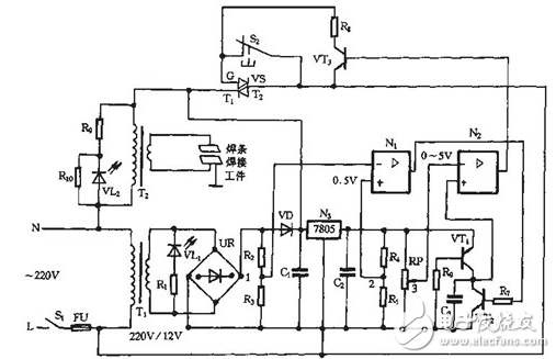
The figure shows a spot welding machine main circuit and control circuit. Among them, the load controlled by the bidirectional thyristor is a miniature spot welder for welding thin metal sheets. When working, welding transformer T2 secondary side and welding work group or closed circuit. Hundreds of Abe's currents are instantaneously passed through the electrodes and concentrated on tiny solder joints, which generate high heat, melt the metal, and complete the soldering. As shown below.
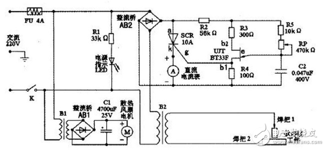
B2 is a step-down transformer. It is also the core part of the welding machine. AB2 rectifier bridge, unidirectional thyristor SCR, single-junction transistor UJT, resistors R2, R3, R4, R5, capacitor C2 and potentiometer RP constitute a stepless welding current regulator. DC ammeter A is used to indirectly indicate the size of the welding working current. A power indicator circuit is formed with the LED. The small transformer B1, the rectifier bridge AB1, the capacitor C1, and the fan M constitute a heat dissipation system.
It can be seen from the figure that the circuit of the device is very concise. To be complicated, it can only be considered as a current regulator. It uses the negative resistance characteristic of a single-junction transistor to form a relaxation oscillator as a trigger circuit for a one-way thyristor. The power of the single-junction transistor relaxation oscillator is taken from the full-wave ripple DC voltage output from the Bridge Rectifier circuit. When the SCR is not turned on, the capacitor C2 of the relaxation oscillator is charged by R2, R5 and RP, and the voltage VC2 across the capacitor rises exponentially. When the peak voltage of the single-junction transistor is VP. The single-junction transistor UJT suddenly turns on and the base resistor RB1 drastically decreases. The capacitor C2 is quickly discharged through the PN junction to the resistor R4, causing a positive transition of the voltage Vg across R4. A steep rising edge of the pulse is formed. As the capacitor C2 discharges, VC2 decreases exponentially, and when it is lower than the valley voltage V, the single junction transistor is turned off.
Outputs at both ends of R4 are tip trigger pulses. The thyristor SCR is turned on. An alternating current flows in the primary winding of B2, and the voltage drop across the thyristor becomes very small, forcing the relaxation oscillator to stop working. When the AC voltage crosses zero, the thyristor is forced to turn off. The relaxation oscillator gets power again, and the capacitor C2 starts charging again, so that the above process is repeated continuously. Adjusting the potentiometer RP can change the charging time of the capacitor C2, that is, changing the oscillation period of the relaxation oscillator. Naturally, the timing of the first trigger pulse emitted by the relaxation oscillator after each AC voltage zero crossing is changed. Correspondingly, the thyristor SCR's conduction control angle is changed so that the voltage applied across the B2 primary winding changes. Ultimately, the purpose of regulating and controlling the secondary output current is achieved.
Device selection and testing
The step-down transformer B2 uses the filament transformer of a waste color television transmitter sound-end high-power amplifier electron tube FU-720F. Primary AC voltage 220V. Secondary AC voltage 4V. Stable output current up to 80A. If you can not find such a suitable low voltage and high Current Transformer, you can also make it yourself. First, look for a 220V AC Power Transformer with a power above 300W and remove the original secondary winding coil. Another copper cable of 0,5 square centimeters or more is used to wind 6 to 10 turns of the transformer to ensure that the output voltage is about 4V.
The single-junction transistor uses BT33F, and the one-way thyristor uses CR10AM. Before the actual fabrication, it is necessary to check the quality and distinguish the lead electrodes. For single junction transistors. First determine the emitter e, the pointer multimeter resistance file placed in RX1k file, with two pens measured any two electrodes between the positive and negative resistance are equal (about 2 ~ 1OkΩ), the two electrodes is b1 And b2, the remaining one electrode is the emitter e, then the first base b1 and the second base b2 are distinguished, the black pen is connected to the E-pole, and the red pens are used to sequentially contact the other two electrodes to measure the forward resistance respectively. value. Due to the structural reasons of the tube, the second base b2 is close to the PN junction, so the forward resistance between the emitters e and b2 should be slightly smaller than the forward resistance between e and b1, and the range is several to ten kΩ. Therefore, when the measured resistance is small, the electrode connected to the red lead is b2. When the resistance is large, the red pen is connected to b1. However, even if b1, b2 get reversed. Under normal circumstances it will not damage the pipe. Only affect the amplitude of the output pulse; if the output pulse amplitude is found to be small. Just swap two bases on it.
The one-way thyristor looks exactly like a high-Power Transistor. Determine the anode (a), cathode (k), and gate (g) three electrode pins. Use an analog multimeter R&TImes; 10 files. Measure resistance and the other two legs
No poles (more than a few hundred kiloohms of positive and negative resistance) are A poles. Retest the remaining two feet to ask the resistance. The resistance is small (about tens or hundreds of Euro). The black pen is connected to the g pole. The other foot is k pole. If the test results do not match the above conditions. The component is bad.
The DC ammeter A can be replaced with an easy-to-use milliampere meter followed by a long wire. The wire is equivalent to a small resistance shunt resistor. The specific length should be determined after proper pruning according to the actual display conditions. The cooling fan uses a common DC 12V computer fan, and the transformer B1 secondary can take 10V. Resistance should be selected more than 2W, FU selected 250V, 4A fuse. Considering that the secondary output current is relatively large, the copper wire of the welding handle should adopt the copper core wire, and it must have enough cross-section to ensure that it will not be hot due to overload during use.
The last thing to draw attention to is that after the circuit is assembled, it should be placed in a suitable metal shell. In addition to ensuring good ventilation, the entire circuit must be well insulated from the shell, and the shell must be reliably grounded.
The above is the Spot welder control board circuit diagram we have listed for you. You can submit the following form to obtain more industry information we provide for you.
You can visit our website or contact us, and we will provide the latest consultation and solutions
Send Inquiry
Most Popular
lastest New
Related Products
Send Inquiry
Tel: 86-514-87782298
Whatsapp: +8613805278321
Address: 3rd Floor, Weiheng Building No.20 B Area, Yangzhou, Jiangsu China
Website: https://www.yzpst.com
Privacy statement: Your privacy is very important to Us. Our company promises not to disclose your personal information to any external company with out your explicit permission.
Fill in more information so that we can get in touch with you faster
Privacy statement: Your privacy is very important to Us. Our company promises not to disclose your personal information to any external company with out your explicit permission.