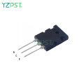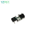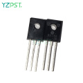


85A Electronic cigarette lighter Mosfet Load 85N03
$0.299≥1000Piece/Pieces
| Payment Type: | L/C,T/T,Paypal |
| Incoterm: | FOB,CFR,CIF |
| Min. Order: | 1000 Piece/Pieces |
| Transportation: | Ocean,Air |
| Port: | Shanghai |

$0.299≥1000Piece/Pieces
| Payment Type: | L/C,T/T,Paypal |
| Incoterm: | FOB,CFR,CIF |
| Min. Order: | 1000 Piece/Pieces |
| Transportation: | Ocean,Air |
| Port: | Shanghai |
Model No.: YZPST-85N03
Brand: YZPST
Type: Intrinsic Semiconductor
| Selling Units | : | Piece/Pieces |
| Package Type | : | 1. Anti-electrostatic packaging 2. Carton box 3. Plastic protective packaging |
Electronic cigarette lighter Mosfet
YZPST-85N03
85A Electronic cigarette lighter Mosfet Load Switch Mosfet 85N03
| VDSS30V RDS(ON) 2.3mΩ(max.)@ VGS=10V RDS(ON) 3.0mΩ(max.)@ VGS=4.5V ID 85A |
|
| Description | DFN5X6-8L |
|
YZPST85N03 uses advanced Trench technology and designs to provide excellent RDS(ON) with low gate charge. This device is suitable for use in PWM, load switching and general purpose applications. |
|
| Applications | Features |
| ■ Lithium-Ion Secondary Batteries ■ Load Switch ■ DC-DC converters and Off-line UPS | ■ Low On-Resistance ■ Low Input Capacitance ■ Low Miller Charge ■ Low Input / Output Leakage |
| Absolute Maximum Ratings (TA=25°C unless otherwise noted) | |||
| Parameter | Symbol | Value | Unit |
| Drain-Source Voltage | VDSS | 30V | V |
| Gate-Source Voltage | VGSS | ±20V | V |
| Drain Current-Continuous @ TC=25℃ NOTE 3 |
ID | 85 | A |
| Drain Current-Continuous @ TC=100℃ NOTE 3 | 68 | A | |
| Drain Current-Pulsed NOTE 1 | IDM | 320 | A |
| Avalanche Current, L=0.1mH | IAS | 50 | A |
| Avalanche Energy, L=0.1mH | EAS | 125 | mJ |
| Maximum Power Dissipation @ TC=25℃ |
PD | 60 | W |
| Maximum Power Dissipation @ TA=25℃ | 5.7 | W | |
| Storage Temperature Range | TSTG | -50 to 150°C | °C |
| Operating Junction Temperature Range | TJ | -50 to 150°C | °C |
| Thermal Resistance Ratings | ||||||
| Parameter | Symbol | Conditions | Min. | Typ. | Max. | Unit |
| Maximum Junction-to-Ambient NOTE2 | RθJA | Steady State | - | - | 22 | °C/W |
| Maximum Junction-to-Case | RθJC | Steady State | - | - | 2.1 | °C/W |
| Electrical Characteristics(TJ=25°C unless otherwise noted) | ||||||
| Parameter | Symbol | Conditions | Min. | Typ. | Max. | Unit |
| OFF CHARACTERISTICS | ||||||
| Drain-Source Breakdown Voltage | BVDSS | VGS=0V , IDS=250uA | 30 | - | - | V |
| Zero Gate Voltage Drain Current | IDSS | VDS=30V, VGS=0V | - | - | 1 | uA |
| Gate-Source Leakage Current | IGSS | VGS=±20V , VDS=0V | - | - | ±100 | nA |
| ON CHARACTERISTICS | ||||||
| Gate Threshold Voltage | VGS(TH) | VGS=VDS, IDS=250uA | 1.2 | - | 2.5 | V |
|
Drain-Source On-Resistance |
RDS(ON) | VGS=10V , IDS=16A | - | 1.75 | 2.3 |
mΩ |
| VGS=4.5V , IDS=16A | - | 2.6 | 3.0 | |||
| DYNAMIC CHARACTERISTICS | ||||||
| Input Capacitance | Ciss |
VDS=10V, VGS=0V, f=1MHz | - | 5910 | - |
pF |
| Output Capacitance | Coss | - | 725 | - | ||
| Reverse Transfer Capacitance | Crss | - | 537 | - | ||
| SWITCHING CHARACTERISTICS | ||||||
| Turn-On Delay Time | Td(on) |
VDS=15V, VGS=10V, ID=1A , RGEM=3.3Ω | - | 20 | - |
ns |
| Rise Time | tr | - | 6.5 | - | ||
| Turn-Off Delay Time | Td(off) | - | 122 | - | ||
| Fall Time | tf | - | 15 | - | ||
| Total Gate Charge at 4.5V | Qg |
VDS=15V, IDS=16A, VGS=10V | - | 54 | - |
nC |
| Gate to Source Gate Charge | Qgs | - | 18 | - | ||
| Gate to Drain "Miller" Charge | Qgd | - | 20.5 | - | ||
| SWITCHING CHARACTERISTICS | ||||||
| Drain-Source Diode Forward Voltage | VSD | VGS=0V, IS=4A | - | - | 1.3 | V |
| Body Diode Reverse Recovery Time | trr | If=10A, dl/dt=100A/μs, TJ=25°C | - | 46 | - | ns |
| Body Diode Reverse Recovery Charge | Qrr | - | 38 | - | nC | |
Notes:
1. Pulse Test: Pulse Width ≦300μs, Duty Cycle≦ 2%.
2. RΘJA is the sum of the junction-to-case and case-to-ambient thermal resistance where the case thermal reference is defined as the solder mounting surface of the drain pins. RΘJC is guaranteed by design while RΘCA is determined by the user`s board design. RΘJA shown below for single device operation on FR-4 in
still air.
3. The maximum current rating is limited by package.
")
")
")
")


Tel: 86-514-87782298
Whatsapp: +8613805278321
Address: 3rd Floor, Weiheng Building No.20 B Area, Yangzhou, Jiangsu China
Website: https://www.yzpst.com


Privacy statement: Your privacy is very important to Us. Our company promises not to disclose your personal information to any external company with out your explicit permission.
Fill in more information so that we can get in touch with you faster
Privacy statement: Your privacy is very important to Us. Our company promises not to disclose your personal information to any external company with out your explicit permission.