


Please Leave Us A Message
Privacy statement: Your privacy is very important to Us. Our company promises not to disclose your personal information to any external company with out your explicit permission.

 May 06, 2019
introduction
Bidirectional thyristor is a kind of Power Semiconductor Device, also known as bidirectional thyristor. It can be used as a power driving device in the single-chip microcomputer control system. Since the triac has no reverse voltage withstand and the control circuit is simple, it is especially suitable for AC. The contact switch is used. The two-way thyristor is generally connected to some high-powered electrical appliances, and is connected in a strong electric network. The anti-interference problem of the trigger circuit is very important, usually triggered by the optocoupler in the single-chip control system. The signal is applied to the gate of the thyristor. In order to reduce the driving power and the interference generated when the thyristor is triggered, the triggering of the bidirectional thyristor of the AC circuit often adopts a zero-crossing trigger circuit. Zero-crossing triggering refers to turning on at a moment near zero or zero. The above circuit also requires a sinusoidal AC zero-crossing detection circuit due to the use of zero-crossing triggering.
1 zero crossing detection circuit
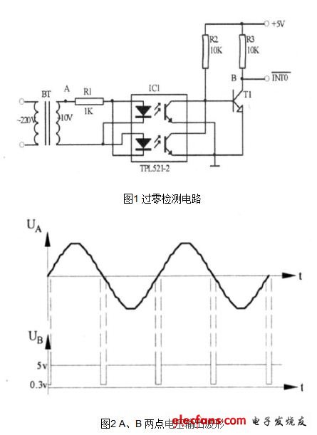
The circuit design is shown in Figure 1. In order to improve the efficiency, the trigger pulse is synchronized with the AC voltage. It is required to output a trigger pulse every half AC cycle, and the trigger pulse voltage should be greater than 4V, and the pulse width should be greater than 20us. For the transformer, the TPL521-2 is an optocoupler that acts as an isolation. When the sinusoidal AC voltage is close to zero, the two LEDs of the photocoupler are turned off, and the bias resistor potential of the base of the transistor T1 is turned on to generate a negative pulse signal, and the output terminal of T1 is connected to the external interrupt 0 of the single chip microcomputer 80C51. Input pins to cause an interrupt. The timer is used to accumulate the phase shift time in the interrupt service subroutine, and then the synchronous trigger signal of the triac is issued. The voltage output waveforms of the zero-crossing detection circuits A and B are shown in Figure 2.
2 zero-crossing trigger circuit
The circuit is shown in Figure 3. In the figure, MOC3061 is a photoelectrically coupled triac driver. It is also a type of optocoupler used to drive the triac BCR and act as an isolation. R6 is the trigger current limiting resistor. R7 is a BCR gate resistor to prevent false triggering and improve anti-interference ability. When the P1. 0 pin of the single-chip microcomputer 80C51 outputs a negative pulse signal, T2 is turned on, and MOC3061 is turned on, triggering BCR to turn on, and the AC load is turned on. In addition, if the bidirectional thyristor is connected to the inductive AC load, since the power supply voltage leads the load current by a phase angle, when the load current is zero, the power supply voltage is a reverse voltage, and the inductive load self-induced electromotive force el acts. The triac is subjected to voltages that far exceed the supply voltage. Although the two-way thyristor is reverse-conducting, it is easy to break down, so the triac must be able to withstand this reverse voltage. Generally, an RC resistor-capacitor absorbing circuit is connected in parallel between the two-way thyristor to realize bidirectional thyristor over-voltage protection. C2 and R8 in Fig. 3 are RC RC absorption circuits.

3 Conclusion
The two-way thyristor zero-crossing trigger circuit is mainly applied to the AC load control circuit of the single-chip control system, and can control high-power AC equipment such as electric furnace and AC motor. It has been proved that the work is safe and reliable. This article focuses on zero-crossing detection and trigger circuits. As for the software design is relatively simple, when the zero-crossing detection circuit detects a zero-crossing, an interrupt request is generated. As long as the trigger pulse is issued through the P1. 0 pin of the single-chip microcomputer 80C51 in the interrupt service routine, the triac conduction can be triggered, which is limited in space. , will not repeat them here.
The above is the Design of two-way thyristor zero-crossing detection circuit we have listed for you. You can submit the following form to obtain more industry information we provide for you.
You can visit our website or contact us, and we will provide the latest consultation and solutions
Send Inquiry
Most Popular
lastest New
Send Inquiry
Tel: 86-514-87782298
Whatsapp: +8613805278321
Address: 3rd Floor, Weiheng Building No.20 B Area, Yangzhou, Jiangsu China
Website: https://www.yzpst.com
Privacy statement: Your privacy is very important to Us. Our company promises not to disclose your personal information to any external company with out your explicit permission.
Fill in more information so that we can get in touch with you faster
Privacy statement: Your privacy is very important to Us. Our company promises not to disclose your personal information to any external company with out your explicit permission.