


Please Leave Us A Message
Privacy statement: Your privacy is very important to Us. Our company promises not to disclose your personal information to any external company with out your explicit permission.

 April 25, 2019
In recent years, the demand for energy-efficient, high-power systems in the switching power supply market has continued to increase, and designers have turned to finding converter topologies with lower power losses. PWM Phase Shift Control Full-Bridge Converter is one of the popular soft-hard switching power supply topologies that achieve high energy efficiency at high power. This paper aims to investigate the operating characteristics of MOSFET switching transistors in zero-voltage switching (ZVS) converters.
1 IntroductionMarket positioning for zero-voltage switching phase-shift converters includes telecom equipment power supplies, mainframes or servers, and other electronic devices that require both power density and energy efficiency. To achieve this goal, it is necessary to minimize power loss and reactive power. It is a feasible way to increase the switching frequency of the converter, but high switching frequency will cause the switching loss to rise, which is contrary to the goal of improving energy efficiency. An effective solution is to use a zero-voltage switch (ZVS) or zero-current-switch (ZCS) converter topology. This method ensures that the switch is zero-voltage or zero-current before the state transition. Especially worth mentioning is the zero-voltage switch. The method can ensure that the switch tube has zero voltage across the front tube before the conduction, thereby eliminating the power loss caused by the overlap of the switch current and the voltage waveform. The zero-crossing switching method has many advantages, such as linear control constant frequency operation, integration of stray capacitance or resistance in the power circuit, and low EMI electromagnetic interference, but there are many disadvantages, for example, the phase shift controller has a complicated design and the rectifier tube oscillates. Frequency and overshoot, soft switching losses under light load conditions. Recently, the introduction of integrated controllers has reduced the complexity of phase shift controller design, and the selection of dedicated switch tubes can solve the problem of light load switch power consumption. Certain electrical characteristics of the MOSFET help the system reduce the probability of failure. This article describes the switch sequence with the highest probability of failure.
2. Zero voltage switch topology introductionThe basic phase shifting circuit is composed of four switching tubes, each of which has two switching tubes. Because of the working mode, the switching tubes of the two bridge arms do not change state at the same time, and always one bridge arm changes the switching state before the other bridge arm. The first to change the state is often referred to as the "leading bridge arm" and the other is referred to as the "lag bridge arm." As shown in Fig. 1, the switching tubes Q1 and Q2 represent "leading bridge arms", and the switching tubes Q3 and Q4 represent "lag bridge arms".

Figure 1: Phase-shifted zero-voltage switch full-bridge circuit
The output power can be controlled by setting the phase shift time. Specifically, the output power is large, and the phase shift time is set to be shorter; the output power is small, and the phase shift time is set longer. This method can control the switching phase.

Figure 2. Commutation sequence
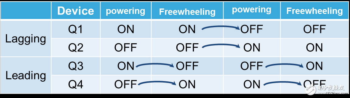
Looking at the sequence of signals shown in Figure 2, it is not difficult to understand that the Q3 and Q4 switch tubes are switched on after the other two switch tube switches are completely closed. In other words, the on or off action of the "leading bridge arm" switches Q1 and Q2 always occurs before the "lag bridge arm" switches Q3 and Q4. Because of the switching sequence, the "leading bridge arm" switch must undergo a freewheeling phase, and the "lag bridge arm" switch tube did not find this process. The following table is the switch sequence table.
Table 1.
This control method can reduce the switching loss because it is turned on only when the voltage across the switch is zero. Figure 3 shows the current and voltage waveforms of a typical phase-shifted (PS) zero-voltage switching converter.

Figure 3. Typical waveform of a phase-shifted ZVS FB DC-DC converter
Looking at the highlight of Figure 3, it is not difficult to find that the Q4 current signal is composed of two parts. The first part of the current flows through the channel between the source and the drain of the switching transistor and the body effect diode, while the second part of the current flows only through the internal channel between the drain and the source of the MOSFET. As the polarity of the transformer voltage changes, the current direction reverses immediately. Hysteresis bridge arm switch Q2 (please check the original to see if there is a clerical error) Use this switch sequence to change the switch state when zero crossing, and start to conduct when the voltage at both ends is zero, realize zero voltage switch operation. Pay attention to the signal of the Q4 switch tube, especially the current signal. When the current changes direction, the voltage decreases. Since the current is composed of two parts, the time (trr) taken to remove minority carriers in the body effect diode is shorter than the typical test time. The concentration of minority carriers is mainly related to the lifetime of the recombination. Therefore, it is recommended that this topology use a switching tube with a fast reverse recovery speed. Below we explore the potential failures caused by this problem.
3. Potential failure of the switchAs described above, during the zero-voltage switching state transition process, the internal body diode of the MOSFET switch Q4 participates in the switching operation, and the on-time is determined by the magnitude of the load. In order to adjust the output current, the phase shift time between the two bridge arms is variable, so the body effect diode conduction time changes from a short time at high power to a light load for a short time.
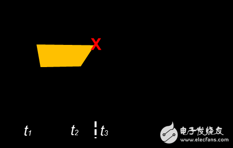
Figure 4. Typical waveforms at heavy load

Figure 5. Typical waveform at light load
Let us compare the two cases. The light carrier condition of Figure 5 is less than the time required for the reloading of the minority carrier reorganization, which may be shorter than the time required to complete the whole operation. Looking closely at this example, we find that light loads are the most critical condition for this risk.
As shown in Figure 6, the red dashed line represents a different recovery time, indicating a situation where a failure may occur when a suitable device is not used. We simulate three different recovery times with three different lines, two of which represent a safety situation and a third one that represents a possible failure. In the last case, the recovery time is not enough to allow the minority carriers inside the MOSFET to fully recover.
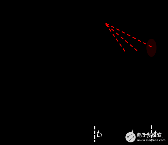
Figure 6. Typical waveform on the lead switch
In order to reduce the risk of failure caused by this electrical stress, the MOSFET switch with two smaller parameters, trr and Qrr, should be selected. We introduced several semiconductor technologies that solve the fault mode of the ZVS topology. There are several MOSFETs with short reverse recovery time and strong dv/dt tolerance, which are suitable for higher frequency ZVS full bridge applications. These methods also allow switching power supply manufacturers to increase the reliability of their power systems. Figure 6 shows the current waveform of the switching tube of the leading bridge arm. We can also do a similar analysis of the lag bridge switch. Unlike the switching tube of the leading bridge arm, the conduction phase of the hysteresis bridge switching tube includes the reverse recovery operation of the internal body effect diode. In this case, if the same switch tube as the lead bridge arm is selected, there will be no problem (Fig. 7) because the lag bridge arm switch tube has more time for reverse reverse recovery.
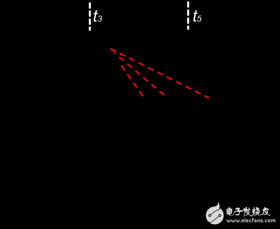
Figure 7. Typical waveform on the hysteresis switch
4 ConclusionThis article explores the potential failure risk of MOSFET transistors in phase-shifted zero-voltage switching converters. By analyzing the switching state transition order of this particular topology, this paper focuses on the key operating conditions under which faults can occur, as well as the locations most sensitive to electrical stress within this topology. According to the switching sequence, this topology is divided into two parts: “leading bridge arm” and “lag bridge arm”. This paper discusses some electrical characteristics of MOSFET transistors and also proposes a product selection idea. In the selection of the type, the advance bridge arm must be considered for the trr and Qrr restrictions. Choosing the right switch tube can improve system reliability, reduce the probability of switch tube failure, and achieve a robust and reliable design.
Discuss the operating characteristics of MOSFET switching transistors in zero-voltage switching (ZVS) converters
The above is the Discuss the operating characteristics of MOSFET switching transistors in zero-voltage switching (ZVS) converters we have listed for you. You can submit the following form to obtain more industry information we provide for you.
You can visit our website or contact us, and we will provide the latest consultation and solutions
Send Inquiry
Most Popular
lastest New
Send Inquiry
Tel: 86-514-87782298
Whatsapp: +8613805278321
Address: 3rd Floor, Weiheng Building No.20 B Area, Yangzhou, Jiangsu China
Website: https://www.yzpst.com
Privacy statement: Your privacy is very important to Us. Our company promises not to disclose your personal information to any external company with out your explicit permission.
Fill in more information so that we can get in touch with you faster
Privacy statement: Your privacy is very important to Us. Our company promises not to disclose your personal information to any external company with out your explicit permission.