


Please Leave Us A Message
Privacy statement: Your privacy is very important to Us. Our company promises not to disclose your personal information to any external company with out your explicit permission.

 April 19, 2019
With the evolution of hybrid electric and electric vehicle technology, inverter drive technology has entered the automotive field, from low-power applications such as air conditioners and heating systems, to high-power applications such as drive and regenerative braking systems, all of which The commonality is the need to maximize the operating life by protecting the power switching transistors in the inverter design.
This article refers to the address: http://
Inverters in automotive systems are a key component of motor-controlled power supplies that convert relatively low DC battery voltages into AC high voltages, where power switches are used to regulate energy delivery, see Figure 1. The switching signal is sent through the microcontroller and the isolation gate driver is used as an interface between the low voltage microcontroller and the high voltage power switch.
Many new forms of power switches, such as silicon carbide, have been evaluated for use in automotive inverters, but the most competitive ones are IGBTs. These power transistors have been widely used in high voltage and high power processing for a long time, but there are disadvantages in the development process. In order to minimize the power loss in the IGBT, a new generation of IGBT products seeks to reduce switching and conduction. Loss, however, in order to reduce transmission losses, concessions must often be made on the basis of robustness.
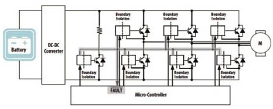
Figure 1 Inverters in automotive systems use power switching IGBT devices to control motor power, but these devices must be protected to ensure long operating life.
Error protection to avoid damage
Reducing the IGBT conduction loss usually causes an increase in the short-circuit current, thereby reducing the short-circuit survival time. Many internal or external error conditions of the inverter may cause one or more IGBT short-circuit or similar short-circuit overload conditions in the inverter, including phase. Short circuit to phase output, overshoot of inverter bridge pin, and low IGBT drive voltage. Since IGBTs are damaged by these errors, fast and reliable IGBT short-circuit detection and protection becomes very important for inverter design.
But not all of these errors can be detected using phase current sensors. A good alternative is to independently detect the load current of each IGBT. There are several ways to detect the magnitude of the load current. For example, a shunt resistor or an emitter-separated IGBT can generate a voltage signal proportional to the IGBT load current. When the signal exceeds the set threshold, the protection mechanism is triggered. However, the maximum tolerable current of the IGBT depends on the process, operating temperature and gate voltage used. Therefore, it must be very conservative when setting the load current trigger threshold to limit the operating range of the IGBT.
The third method is to detect the time when the IGBT is out of saturation by monitoring the collector-to-emitter voltage (VCE). Under normal operation, the IGBT is in saturation mode and VCE is low, when an output short circuit or low gate drive occurs. IGBT will enter linear mode and VCE rises, causing excessive power loss to cause device failure. Detection of this desaturation (DESAT) condition can achieve the same error detection result as monitoring output current, but it can monitor the real working condition of IGBT and effectively reduce The advantages of many external factors interfere with the use of IGBTs with higher power.
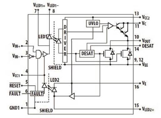
Figure 2 integrates error detection and soft-shutdown. Avago's ACPL-38JT IGBT gate drive optocoupler solves the error conditions that can damage the inverter's power switch.
Equally important to detecting errors is the inherent resolution of the inverter itself. When an error condition is detected, there is a high probability that a large current will pass. If the IGBT is turned off too fast, then a rapid current change (di/dt) And the inevitable connection of parasitic inductance may cause the reflow EMF to exceed the maximum voltage tolerance of the IGBT, causing damage to the IGBT and destroying the overcurrent protection mechanism. This problem can be mitigated by implementing a soft turn-off of the IGBT, which reduces the rate of change of the voltage by prolonging the gate discharge time at which the error occurs.
Error resolving power also has system considerations. Automatic error detection can be configured to turn off all other gate drivers at the same time. On the other hand, error detection can also be designed to independently detect and turn off each IGBT, allowing for normal fit. A gentle error handling and shutdown strategy for automotive traction applications. Automatic error detection can also include providing signals to the microcontroller responsible for managing the automotive powertrain for additional response options.
Reliability is the basic requirement
There are several key points in implementing these error detection and IGBT protection circuits in automotive systems, including low cost, small size, and ruggedness. Because automotive applications are generally much more demanding for quality and reliability than many other consumer and industrial applications, ruggibility is important, further, in more harsh environments, including extremely wide operating temperature conditions and high radiation. And inductive electromagnetic noise must have higher reliability.
A highly integrated solution, as shown in Figure 2, Avago's ACPL-38JT gate drive optocoupler integrates multiple functions such as saturation-detection and undervoltage lockout (UVLO) circuits, as well as isolated error signals and soft-shutdown. All of these needs are met in the IGBT gate driver. Avago's optical isolation features include transparent Faraday shielding around the optical receiver to help reduce electromagnetic noise coupling, and the use of specially designed LEDs to ensure longer operating life at high temperatures, and built-in protection circuitry saves several discrete components and reduces cost. And improve system reliability by addressing all error conditions, including low gate drive voltages that can damage the power switching transistors.
The use of a single integrated device on the gate drive and IGBT protection circuitry also helps to improve system reliability by eliminating discrete device failure points. In addition, integrated devices can help shorten designs and pass through complete and pre-tested designs. Regulatory review time. For example, the ACPL-38JT is manufactured and tested in accordance with the TS 16949 and AEC-Q100 automotive guidelines and operates over a temperature range of -40°C to 125°C.
As the role of high-power electrical systems in automotive design becomes more and more important, fault protection becomes a necessary condition for ensuring long working life. Power switch use in inverter design also provides integration of detection and response mechanisms. The solution can meet this demand in a compact, low-cost and highly reliable way.
The above is the How to protect power transistors in automotive inverter design we have listed for you. You can submit the following form to obtain more industry information we provide for you.
You can visit our website or contact us, and we will provide the latest consultation and solutions
Send Inquiry
Most Popular
lastest New
Related Products
Send Inquiry
Tel: 86-514-87782298
Whatsapp: +8613805278321
Address: 3rd Floor, Weiheng Building No.20 B Area, Yangzhou, Jiangsu China
Website: https://www.yzpst.com
Privacy statement: Your privacy is very important to Us. Our company promises not to disclose your personal information to any external company with out your explicit permission.
Fill in more information so that we can get in touch with you faster
Privacy statement: Your privacy is very important to Us. Our company promises not to disclose your personal information to any external company with out your explicit permission.