YANGZHOU POSITIONING TECH CO., LTD.
Home> Industry Information> Basic requirements for thyristor trigger circuits

Basic requirements for thyristor trigger circuits

April 03, 2019

Probe current voltage pin 420*4450 head diameter 5.0 over current current and voltage pin
GW MB10F 0.8A 1000V rectifier bridge
Industrial Router Crystal 3.2*2.5mm 3225 26M (26.000MHZ) 12PF 10PPM 20PPM 30PPM
MOS power IC full range

In order to turn the thyristor from off to on, it must have certain external conditions, that is, the thyristor anode is applied with a forward voltage and a positive control signal is applied to the gate. When the thyristor is turned on, the control signal does not work. Until the power supply crosses zero, its anode current is less than the holding current, and the thyristor turns itself off.
Since the gate is out of control after the thyristor is turned on, the control of the thyristor actually provides a threshold control with a certain width to trigger the thyristor to turn it on. The gate control circuit is often referred to as a trigger circuit.
The basic requirements for the thyristor trigger circuit are:
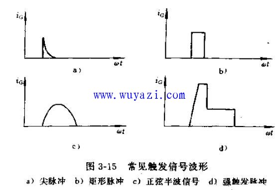
1. The trigger signal can be AC, DC or pulse t. The trigger signal can only be active when the gate is extremely positive and the cathode is negative. In order to reduce the loss of the gate, the trigger signal is often in the form of a pulse. The common trigger signal waveform is as shown in the figure.

Basic requirements for thyristor trigger circuits
2. The trigger pulse should have sufficient power. The trigger voltage and trigger current should be greater than the gate trigger voltage and gate trigger current of the thyristor. Because the characteristics of the thyristor have large dispersion, and the characteristics vary with temperature, when designing the trigger circuit, the power of the trigger signal should be left to ensure reliable triggering of the transistor, and of course, the signal can not exceed the gate. Extreme limit parameter values (general VCm<10V, IGM<10A).
3. The phase shift range of the trigger pulse should meet the requirements of the converter device. The phase shift range of the trigger pulse is related to the main circuit type, the load nature and the use of the converter device. For example, a three-phase half-wave rectification circuit requires a phase shift range of 150° in the case of an electric nozzle load; Fully controlled rectifier circuit, the phase shift range of the resistive load is 120°. If the three-phase full control bridge works in the rectification or inverter state and supplies power to the inductor, the phase shift range is required to be 0~180°. In practical application In order to normal operation of the device, there are sometimes restrictions on αmin and βmin, so the actual range is less than 180°.
4. The width and steepness of the trigger pulse. The width of the trigger pulse should generally ensure that the thyristor anode current can reach the holding current before the pulse disappears, so that the thyristor can remain in the on state, which is the minimum allowable width. The pulse width is also related to the nature of the load and the main circuit type. For example, for a single-phase rectification circuit, the pulse width is required to be greater than 10 μs for resistive loads and greater than 100 μs for inductive loads. For the dry three-phase full-control bridge circuit, the pulse width should be 60°~120° with single pulse triggering. The pulse width of the double pulse can be about 10°. The steeper the steepness of the leading edge of the trigger pulse, the more favorable the simultaneous triggering of the parallel or series thyristor. Generally, the leading edge of the trigger pulse is steeper than lOV/us or 800mA/us.
5. The trigger pulse must be synchronized with the main loop supply voltage. In order to enable the thyristor to repeatedly trigger on the same phase every cycle, to ensure the quality and reliability of the converter, the trigger pulse must maintain a certain fixed phase relationship with the main circuit supply voltage. The method in which the god trigger pulse maintains a fixed phase relationship with the main loop power source is called synchronization.

The above is the Basic requirements for thyristor trigger circuits we have listed for you. You can submit the following form to obtain more industry information we provide for you.

You can visit our website or contact us, and we will provide the latest consultation and solutions

Share to:

Send Inquiry

Home> Industry Information> Basic requirements for thyristor trigger circuits
苏ICP备05018286号-1
We will contact you immediately

Fill in more information so that we can get in touch with you faster

Privacy statement: Your privacy is very important to Us. Our company promises not to disclose your personal information to any external company with out your explicit permission.

Send